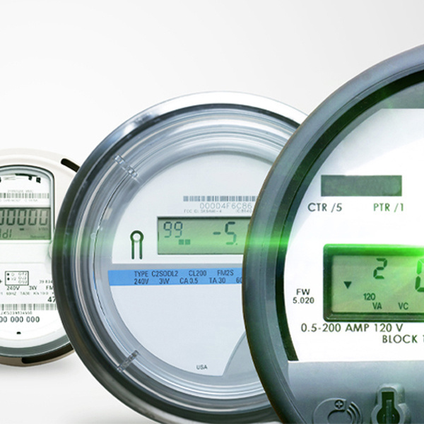
SIDACtor®保护晶闸管

SIDACtor® Device Selection Criteria

When selecting a SIDACtor® device, use the following criteria:

Off-state Voltage (VDRM)

The VDRM of the SIDACtor® device must be greater than the maximum operating voltage of the circuit that the SIDACtor® device is protecting.

Example 1: For a POTS (Plain Old Telephone Service) application, convert the maximum operating Ring voltage (150 VRMS) to a peak voltage, and add the maximum DC bias of the central office battery:

  • 150 VRMS v2 + 56.6 VPK = 268.8 VPK
  • ∴ VDRM > 268.8 V

Example 2: For an ISDN application, add the maximum voltage of the DC power supply to the maximum voltage of the transmission signal (for U.S. applications, the U-interface will not have a DC voltage, but European and Japanese ISDN applications may):

  • 150 VPK + 3 VPK = 153 VPK
  • ∴ VDRM > 153 V

Switching Voltage (VS)

The VS of the SIDACtor® device should be equal to or less than the instantaneous peak voltage rating of the component it is protecting.

Example 1: VS = VRelay Breakdown

Example 2: VS = SLIC VPK

Peak Pulse Current (IPP)

For circuits that do not require additional series resistance, the surge current rating (IPP) of the SIDACtor® device should be greater than or equal to the surge currents associated with the lightning immunity tests of the applicable regulatory requirement (IPK):

  • IPP = IPK

For circuits that use additional series resistance, the surge current rating (IPP) of the SIDACtor® device should be greater than or equal to the available surge currents associated with the lightning immunity tests of the applicable regulatory requirement (IPK(available)):

  • IPP = IPK(available)

The maximum available surge current is calculated by dividing the peak surge voltage (VPK) by the total circuit resistance (RTOTAL):

  • IPK(available) = VPK/RTOTAL

For longitudinal surges (Tip-Ground, Ring-Ground), RTOTAL is calculated for both Tip and Ring:

  • RSOURCE = VPK/IPK
  • RTOTAL = RTIP + RSOURCE
  • RTOTAL = RRING + RSOURCE

For metallic surges (Tip-Ring):

  • RSOURCE = VPK/IPK
  • RTOTAL = RTIP + RRING + RSOURCE

Example 1: A modem manufacturer must pass the Type A surge requirement of TIA-968-A without any series resistance.

  • IPK = 100 A, 10x560 µs
  • IPP = 100 A, 10x560 µs
  • Therefore, either a "B" rated or "C" rated SIDACtor® device would be selected.

Example 2: A line card manufacturer must pass the surge requirements of GR 1089 with 30 O on Tip and 30 O on Ring.

  • IPK = 100 A, 10x1000 µs
  • VPK = 1000 V
  • RSOURCE = VPK/IPK = 10 O
  • RTOTAL = RSOURCE + RTIP = 40 O
  • IPK (available) = VPK/RTOTAL = 1000 V/40 O
  • ∴ IPP = 25 A

Holding Current (IH)

Because TIA-968-A 4.4.1.7.3 specifies that registered terminal equipment not exceed 140 mA dc per conductor under short-circuit conditions, the holding current of the SIDACtor® device is set at 150 mA.

For specific design criteria, the holding current (IH) of the SIDACtor® device must be greater than the DC current that can be supplied during an operational and short circuit condition.

Off-State Capacitance (CO)

Assuming that the critical point of insertion loss is 70 percent of the original signal value, the SIDACtor® device can be used in most applications with transmission speeds up to 30 MHz. For transmission speeds greater than
30 MHz, the new MC series is highly recommended.

Regulatory Requirements

Due to the enormous cost of interrupted service and failed network equipment, telephony service providers have adopted various specifications to help regulate the reliability and performance of the telecommunications products that they purchase. In Europe and much of the Far East, the most common standards are ITU-T K.20 and K.21.

In North America, most operating companies base their requirements on NEBs which contain GR1089 requirements, TIA-968-A (formerly known as FCC Part 68), and UL 60950-1.

This section is a paraphrase of existing documents and does not cover the listed recommendation, standard or regulatory requirements in their entirety. This information is intended to be used only as a reference. For exact specifications, obtain the referenced document from the appropriate source.

SIDACtor® Family Descriptions

Broadband Optimized™ Protection

The Broadband Optimized™ family of products is focused on addressing the performance and regulatory requirements of broadband equipment. The Broadband Optimized family, with its wide range of solutions provides applications with the options needed to address the unique protection needs of DSL equipment (up to VDSL) as well as Ethernet (up to 1000baseT). Optimization is accomplished using proprietary and patented approaches that minimize the negative effects of device capacitance on broadband signals. The Broadband Optimized family provides an overvoltage protection solution that helps applications comply with Telcordia GR-1089 Issue 4, and ITU-T recommendations K.20, K.21, K.44, and K.45.

SLIC Protection

The SLIC family of products is focused on addressing the unique protection needs of SLIC (Subscriber Line Interface Circuit) chip sets. The family offers Fixed Voltage and Battrax® battery tracking protection solutions capable of protecting SLIC devices from transients caused by lightning and AC power cross. The SLIC family provides an overvoltage protection solution that helps applications comply with Telcordia GR-1089 Issue 4, and ITU-T recommendations K.20, K.21, K.44, and K.45.

LCAS Protection

The LCAS family of products is focused on the specialized protection needs of Line Circuit Access Switches (LCAS). This family utilizes a specialized asymmetric design specially formulated for LCAS devices. The LCAS family provides an overvoltage protection solution that helps applications comply with Telcordia GR-1089 Issue 4, and ITU-T recommendations K.20, K.21, K.44 and K.45.

Baseband Protection

The Baseband family of products is focused on addressing the performance and regulatory requirements of baseband telecommunications equipment such as voice, modems, and DS1. They offer an overvoltage protection solution that helps applications comply with Telcordia GR-1089 Issue 4, ITU-T recommendations K.20, K.21, K.44, and K.45, and TIA-968-A.

High Surge Current Protection

The High Surge Current products are a unique family of very robust solid state protection devices intended for use in high exposure environments. This family includes products specifically designed for primary protection such as cell and TO-220 devices. The High Surge Current family also has devices capable of meeting 5kA 8/20µs for use in extreme conditions. For enhanced secondary protection requirements, a D-rated device capable of 1000A 2/10µs is available in a DO-214 package. The High Surge Current Protection family provides an overvoltage protection solution that help applications comply with Telcordia GR-1089 Issue 4, and ITU-T recommendations K.20, K.21, K.44, and K.45.

SIDACtor® Family Application Selector Table

Telecom Application Broadband Optimized ™ Protection SLIC Protection Baseband Protection (Voice-DS1) LCAS Protection High Surge Current Protection
ADSL      
ADSL2/2+        
VDSL        
VDSL2        
HDSL2/4      
ISDN      
Ethernet 10/100/1000BaseT        
PoE        
VoIP FXO        
VoIP FXS        
Negative Ringing SLIC        
Positive & Negative Ringing SLIC        
LCAS Relay        
POTS-Telephone-corded & cordless        
MDC Modem        
PCI Modem        
Multifunction Printer-Fax        
T1/E1/J1 (DS1)      
Security System        
Primary Protection Modules        
Secondary Protection Modules-Strip Protectors      
Low Pair Count Installations        
CATV Power Amplifiers        
Base Stations        

SIDACtor® Construction and Operation

SIDACtor devices are thyristor devices used to protect sensitive circuits from electrical disturbances caused by lightning-induced surges, inductive-coupled spikes, and AC power fault conditions. The unique structure and characteristics of the thyristor are used to create an overvoltage protection device with precise and repeatable turn-on characteristics with low voltage overshoot and high surge current capabilities.

Key Parameters

Key parameters for SIDACtor devices are VDRM, IDRM, VS, IH, and VT (please refer to Figure 1.3 on page 11).

VDRM is the repetitive peak off-state voltage rating of the device (also known as stand-off voltage) and is the continuous peak combination of AC and DC voltage that may be applied to the SIDACtor device in its off-state condition.

IDRM is the maximum value of leakage current that results from the application of VDRM.

Switching voltage (VS) is the maximum voltage that subsequent components may be subjected to during a fast-rising (100 V/µs) overvoltage condition.

Holding current (IH) is the minimum current required to maintain the device in the on state.

On-state voltage (VT) is the maximum voltage across the device during full conduction.

Operation

The device operates much like a switch. In the off state, the device exhibits leakage currents (IDRM) less than 5 µA, making it invisible to the circuit it is protecting. As a transient voltage exceeds the device's VDRM, the device begins to enter its protective mode with characteristics similar to an avalanche diode. When supplied with enough current (IS), the device switches to an on state, shunting the surge from the circuit it is protecting. While in the on state, the device is able to sink large amounts of current because of the low voltage drop (VT) across the device. Once the current flowing through the device is either interrupted or falls below a minimum holding current (IH), the device resets, returning to its off state. If the IPP rating is exceeded, the device typically becomes a permanent short circuit.

Physics

The device is a semiconductor device characterized as having four layers of alternating conductivity: PNPN (Figure 1.2 below). The four layers include an emitter layer, an upper base layer, a mid-region layer, and a lower base layer. The emitter is sometimes referred to as a cathode region, with the lower base layer being referred to as an anode region.

Figure 1.2 Geometric Structure of Bidirectional SIDACtor devices

SIDACtor_Tech

As the voltage across the device increases and exceeds the device's VDRM, the electric field across the center junction reaches a value sufficient to cause avalanche multiplication. As avalanche multiplication occurs, the impedance of the device begins to decrease, and current flow begins to increase until the device's current gain exceeds unity. Once unity is exceeded, the device switches from a high impedance (measured at VS) to a low impedance (measured at VT) until the current flowing through the device is reduced below its holding current (IH).

Overvoltage Protection Comparison

The four most commonly used technologies for overvoltage protection are as follows:

  • SIDACtor® devices
  • Gas Discharge Tubes (GDTs)
  • Metal Oxide Varistors (MOVs)
  • TVS diodes

All four technologies are connected in parallel with the circuit being protected, and all exhibit a high off-state impedance when biased with a voltage less than their respective blocking voltages.

SIDACtor® devices

A SIDACtor® device is a PNPN device that can be thought of as a thyristor device without a gate. Upon exceeding its peak off-state voltage (VDRM), a SIDACtor® device will clamp a transient voltage to within the device's switching voltage (VS) rating. Then, once the current flowing through the SIDACtor® device exceeds its switching current, the device will crowbar and simulate a short-circuit condition. When the current flowing through the SIDACtor® device is less than the device's holding current (IH), the SIDACtor® device will reset and return to its high off-state impedance.

Advantages

Advantages of the SIDACtor® device include its fast response time (Figure 1.1), stable electrical characteristics, long term reliability, and low capacitance. Also, because the SIDACtor® device is a crowbar device, it cannot be damaged by voltage.

Restrictions

Because the SIDACtor® device is a crowbar device, it cannot be used directly across the AC line; it must be placed behind a load. Failing to do so will result in exceeding the SIDACtor® device's maximum on-state current rating, which may cause the device to enter a permanent short-circuit condition.

Applications

Although found in other applications, SIDACtor® devices are primarily used as the principle overvoltage protector in telecommunications and data communications circuits. For applications outside this realm, follow the design criteria in "SIDACtor® Device Selection Criteria".

Gas Discharge Tubes

Gas discharge tubes (GDTs) are either glass or ceramic packages filled with an inert gas and capped on each end with an electrode. When a transient voltage exceeds the DC breakdown rating of the device, the voltage differential causes the electrodes of the gas tube to fire, resulting in an arc, which in turn ionizes the gas within the tube and provides a low impedance path for the transient to follow. Once the transient drops below the DC holdover voltage and current, the gas tube returns to its off state.

Advantages

Gas discharge tubes have high surge current and low capacitance ratings. Current ratings can be as high as
20 kA, and capacitance ratings can be as low as 1 pF with a zero-volt bias.

Applications

Gas discharge tubes are typically used for primary protection due to their high surge rating. However, their low interference for high frequency components make them a candidate for high speed data links.

Metal Oxide Varistors

Metal Oxide Varistors (MOVs) are two-leaded, through-hole components typically shaped in the form of discs. Manufactured from sintered oxides and schematically equivalent to two back-to-back PN junctions, MOVs shunt transients by decreasing their resistance as voltage is applied.

Advantages

Since MOVs surge capabilities are determined by their physical dimensions, high surge current ratings are available. Also, because MOVs are clamping devices, they can be used as transient protectors in secondary AC power line applications.

Applications

Although MOVs are restricted from use in many telecom applications (other than disposable equipment), they are useful in AC applications where a clamping device is required and tight voltage tolerances are not.

TVS Diodes

Transient Voltage Suppressor (TVS) diodes are clamping voltage suppressors that are constructed with back-to-back PN junctions. During conduction, TVS diodes create a low impedance path by varying their resistance as voltage is applied across their terminals. Once the voltage is removed, the diode will turn off and return to its high off-state impedance.

Advantages

Because TVS diodes are solid state devices, they do not fatigue nor do their electrical parameters change as long as they are operated within their specified limits. TVS diodes effectively clamp fast-rising transients and are well suited for low-voltage applications that do not require large amounts of energy to be shunted.

Applications

Due to their low power ratings, TVS diodes are not used as primary interface protectors across Tip and Ring, but they can be used as secondary protectors that are embedded within a circuit.

Overshoot Levels versus dv/dt

Firgure 1.4 below shows a peak voltage comparison between SIDACtor® devices, Gas Discharge Tubes (GDT), Metal-Oxide Varistors (MOVs), and TVS diodes, all with a nominal stand-off voltage rating of 230 V. The X axis represents the dv/dt (rise in voltage with respect to time) applied to each protector, and the Y axis represents the maximum voltage drop across each protector.

Figure 1.4 Overshoot Levels versus dv/dt

Telecommunications Protection

Because early telecommunications equipment was constructed with components such as mechanical relays, coils, and vacuum tubes, it was somewhat immune to lightning and power fault conditions. But as step-by-step switches and digital loop carriers have given way to more modern equipment such as multiplexers, routers, gateways and IP switches, there is an increased need for protecting this equipment against system transients caused by lightning and power fault conditions.

Lightning

During an electrical storm, transient voltages are induced onto the telecommunications system by lightning currents which enter the conductive shield of suspended cable or through buried cables via ground currents.

As this occurs, the current traveling through the conductive shield of the cable produces an equal voltage on both the Tip and Ring conductors at the terminating ends. Known as a longitudinal voltage surge, the peak value and waveform associated with this condition is dependent upon the distance the transient travels down the cable and the materials with which the cable is constructed.

Although lightning-induced surges are always longitudinal in nature, imbalances resulting from terminating equipment and asymmetric operation of primary protectors can result in metallic transients as well. A Tip-to-Ring surge is normally seen in terminating equipment and is the primary reason most regulatory agencies require telecom equipment to have both longitudinal and metallic surge protection.

Power Fault

Another system transient that is a common occurrence for telecommunications cables is exposure to the AC power system. The common use of poles, trenches, and ground wires results in varying levels of exposure which can be categorized as direct power fault, power induction, and ground potential rise.

Direct power fault occurs when a power line makes direct contact to telecommunications cables. Direct contact is commonly caused by falling trees, winter icing, severe thunderstorms, and vehicle accidents. Direct power fault can result in large currents being present on the line.

Power induction is common where power cables and telecommunications cables are run in close proximity to one another. Electromagnetic coupling between the cables results in system transients being induced onto the telecommunications cables, which in turn can cause excessive heating and fires in terminal equipment located at the cable ends.

Ground potential rise is a result of large fault currents flowing to Ground. Due to the varying soil resistivity and multiple grounding points, system potential differences may result.

Lightning

Lightning is one of nature's most common and dangerous phenomena. At any one time, approximately 2,000 thunderstorms are in progress around the globe, with lightning striking the earth over 100 times per second. According to IEEE C.62, during a single year in the United States lightning strikes an average of 52 times per square mile, resulting in 100 deaths, 250 injuries, and over 100 million dollars in damage to equipment property.

The Lightning Phenomenon

Lightning is caused by the complex interaction of rain, ice, up drafts, and down drafts that occur during a typical thunderstorm. The movement of rain droplets and ice within the cloud results in a large build up of electrical charges at the top and bottom of the thunder cloud. Normally, positive charges are concentrated at the top of the thunderhead while negative charges accumulate near the bottom. Lightning itself does not occur until the potential difference between two charges is great enough to overcome the insulating resistance of air between them.

Formation of Lightning

Cloud-to-ground lightning begins forming as the level of negative charge contained in the lower cloud levels begins to increase and attract the positive charge located at Ground. When the formation of negative charge reaches its peak level, a surge of electrons called a stepped leader begins to head towards the earth. Moving in 50-meter increments, the stepped leader initiates the electrical path (channel) for the lightning strike. As the stepped leader moves closer to the ground, the mutual attraction between positive and negative charges results in a positive stream of electrons being pulled up from the ground to the stepped leader. The positively charged stream is known as a streamer. When the streamer and stepped leader make contact, it completes the electrical circuit between the cloud and ground. At that instant, an explosive flow of electrons travels to ground at half the speed of light and completes the formation of the lightning bolt.

Lightning Bolt

The initial flash of a lightning bolt results when the stepped leader and the streamer make connection resulting in the conduction of current to Ground. Subsequent strokes (3-4) occur as large amounts of negative charge move farther up the stepped leader. Known as return strokes, these subsequent bolts heat the air to temperatures in excess of 50,000°F and cause the flickering flash that is associated with lightning. The total duration of most lightning bolts lasts between 500 millisecond and one second.

During a lightning strike, the associated voltages range from 20,000 V to 1,000,000 V while currents average around 35,000 A. However, maximum currents associated with lightning have been measured as high as 300,000 A.

10 Key Facts about Lightning

  1. Lightning strikes the earth on an average of 100 times per second.
  2. Lightning strikes can affect computers and other electronic equipment as far as a kilometer away.
  3. Lightning causes transient overvoltages (very fast electrical surges) on power, data communication, and signal and telephone lines. These surges then carry to and affect vulnerable equipment.
  4. At-risk electronic equipment includes computer and peripheral equipment, building management systems, IP-PBX systems, CATV equipment, fire and security systems, PoE systems, and lighting arrays.
  5. Transient overvoltages can cause instant damage to equipment and its circuitry, leading to costly and lengthy stoppages to operation and latent damage, and can result in breakdowns weeks or months later.
  6. Even equipment in a building with structural lightning protection is still at great risk, as structural protection is designed to prevent damage to the building and to prevent loss of life.
  7. While most businesses are at risk, campus or multi-building sites tend to be especially vulnerable.
  8. Lightning can and does strike in the same place and can strike the same place multiple times. Sites that have suffered once are proven vulnerable and often suffer again within a matter of months.
  9. Protecting electronic systems from transient overvoltage damage costs only a fraction of the cost of damage.
  10. Littelfuse designs and manufactures quality lightning protection equipment.

Surge Waveforms for Various Standards
GR 1089‐Core
ITU-T K.20 and K.21
TIA-968-A (formerly known as FCC Part 68)
IEC 61000-4-2, 4-4 and 4-5 Summary
Mainland China Standard-YD/T 950-1998
Mainland China Standard-YD/T 993-1998
Mainland China Standard-YD/T 1082-2000
Certification and Accreditation Administration
of the People's Republic of China
UL 497
UL 497A
UL 497B
UL 497C
UL 497D
UL 60950-1 2nd Edition

pdf icon SIDACtor Protection Thyristor MC Series TO 92 Datasheet

MC Series TO-92 are low capacitance SIDACtor® devices designed to protect broadband CPE equipment...

SIDACtor Protection Thyristor SDP Biased Series 5x6 QFN Datasheet

SIDACtor Protection Thyristor TwinSLIC Series Modified DO 214 Datasheet

SIDACtor Fixed Voltage TwinSLIC Series Modified DO 214

pdf icon SIDACtor Protection Thyristor High Surge Current Series DO 214 Datasheet

The High Surge Current DO-214 Series are SIDACtor® devices designed to protect equipment located in hostile environments from overvoltage transients...

SIDACtor Protection Thyristor TwinChip Series DO 214 Datasheet

SIDACtor Protection Thyristor TO 92 Datasheet

pdf icon SIDACtor Protection Thyristor DO 15 Datasheet

The SIDACtor Series DO-15 are designed to protect baseband equipment such as modems, line cards, CPE and DSL from damaging overvoltage transients...

SIDACtor Protection Thyristor SMA Datasheet

pdf icon SIDACtor Protection Thyristor 5kA Series TO 218 Datasheet

The 5kA Series are SIDACtor® devices designed to protect equipment located in high exposure environments from severe overvoltage transients...

pdf icon SIDACtor Protection Thyristor DO 214 Datasheet

SIDACtor® Series DO-214AA are designed to protect baseband equipment such as modems, line cards, CPE and DSL from damaging overvoltage transients...

pdf icon SIDACtor Protection Thyristor MC Series Modified TO 220 Datasheet

MC Series Modified TO-220 are low capacitance SIDACtor® devices designed to protect various types of broadband equipment from damaging overvoltage transients...

pdf icon SIDACtor Protection Thyristor MS 013 Datasheet

Asymmetrical Multiport Series are SIDACtor® devices designed to protect LCAS (Line Circuit Access Switch) devices from damaging overvoltage transients...

pdf icon SIDACtor Protection Thyristor Fixed Voltage Series DO 214 Datasheet

Fixed Voltage Series DO-214 are uni-directional SIDACtor® devices designed to protect SLICs (Subscriber Line Interface Circuit) from damaging overvoltage transients...

pdf icon SIDACtor Protection Thyristor MC Multiport Series MS 013 Datasheet

MC Multiport Series MS-013 are low capacitance SIDACtor® devices designed to protect broadband equipment from damaging overvoltage transients...

pdf icon SIDACtor Protection Thyristor Primary Protection Balanced Series Modified TO 220 Datasheet

The SIDACtor® Primary Protection Balanced Series Modified TO-220 are thyristor devices designed for use in primary protection applications...

pdf icon SIDACtor Protection Thyristor Q2L Series 3 3x3 3 QFN Datasheet

Fixed Voltage Q2L Series are uni-directional SIDACtor® devices designed to protect SLICs (Subscriber Line Interface Circuit) from damaging overvoltage transients...

pdf icon SIDACtor Protection Thyristor Q2L Series 3x3 QFN Datasheet

Fixed Voltage Q2L Series are uni-directional SIDACtor® devices designed to protect SLICs (Subscriber Line Interface Circuit) from damaging overvoltage transients...

SIDACtor Protection Thyristor SDP TwinChip Series 3x3 QFN Datasheet

pdf icon SIDACtor Protection Thyristor Modified TO 220 Datasheet

The SIDACtor® Series Modified TO-220 are designed to protect baseband equipment from damaging overvoltage transients...

SIDACtor Protection Thyristor T10B Series DO 201 Datasheet